|
|
|
| 121. Attach the wire end with a drop of CA and a piece of heat shrink tubing. Make sure the servo is in neutral and the elevator is in neutral. |
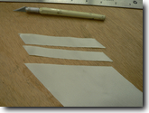
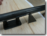
| 122. Prepare two strips of fiberglass cut on a bias (at 45 deg to the fibers) for reinforcing the vertical tail bottom. |
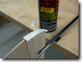
| 123. Attach them to the vertical tail with 3M77. |
| 124. Carefully conform the fiberglass to the surface of the fin and rudder. |
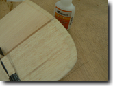
| 125. Wet out fibeglass wit thin CA. |
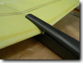
| 126. Mark the position of the wing's leading edge on the hatch cover. |
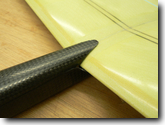
| 127. Trim and sand the rear end of the hatch cover to clear the wing with a small gap between the wing and the hatch cover. |
| NEW! As of July 2009 wing tips are
reinforced with carbon patches for easier throwing peg or blade installation.
Steps 128-133 can be skipped if you have the new wing in your kit. See step 133a for a picture
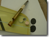
of the new wing tip. 128. To create a hard point for the wing tip throwing peg, use X-acto knife or a toothed brass tube to cut a hole in the wing tip for the round balsa plug. Make two ovals from the suppliled pre-cured carbon patches. |
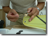
| 129. Mix some 5-min epoxy with microballoons and glue the round balsa plug into the wing. |
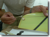
| 130. Remove the epoxy that oozed out of the hole to minimize the amount of required cleaning and sanding later. |
| 131. Trim the round balsa plug down to the wing surface from both sides. |
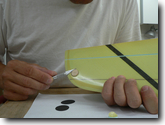
| 132. The balsa plug is trimmed and sanded flush with the wing surface. |
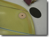
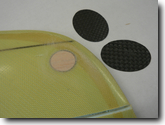
| 133. Glue one patch to the wing over the balsa plug. Drill a pilot hole through the middle of the balsa plug. |
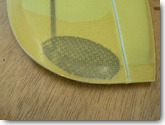
| 133a. NEW! As of July 2009 wing tips are reinforced with carbon patches for easier throwing peg or blade installation. You can skip steps 128-133 related to creating a hard point in the wing and drill a hole for the tip peg directly through the carbon patch in the wing. |
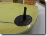
| 134. Glue the second carbon oval over the balsa plug with foam safe CA or laminatng epoxy. Drill a hole through it using the pilot hole on the opposite side of the wing. Insert the throwing peg and glue it with thin CA or laminating epoxy. Thick CA or epoxy will not wick into the joint and will not saturate the balsa. |
| 135. Ballast installation - mark approximate position of the model CG (65mm from the leeading edge). The ballast must be centered around this mark. Insert a round balsa plug into the boom using some measuring stick to limit the depth to the exact required depth for proper ballast positioning. |
|
|
|
| Taboo GT Home | | | News | | | Gallery | | | Construction Notes | | | Building Guide | | | Building Tips | | | Ordering Taboo GT | | | Items For Sale |