
|

|
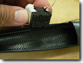
| 106.
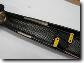
Tape together two fuselage D47 servos (larger servos will have to be staggered). Rough up the bottoms a little. |
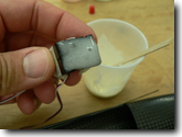
| 107.
Mix 5-min epoxy and apply some to the servos. |
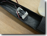
| 108.
Position servos such that you can insert the battery and the receiver into the nose. A small angle gives more space for the servo arms. |
| 109.
Make 2 Z-bends for the pushrod front ends. Attach them to the pushrods with CA and shrink tubing. |
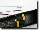
| 110.
The front ends are done. Pushrod housings are trimmed to the right length, and attached to supporting balsa webs. Make balsa webs from 1/16 balsa. The pushrod housing must be well supported to avoid buckling under compression loads. Small gaps are OK as shown on the picture. |
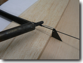
| 111.
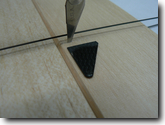
Prepare and install the rudder control horn. Make a slit in the balsa, similar to the aileron horn installation. The height of the horn should be about 14-16mm from the hole to the bottom. |
| 112.
Insert the horn into the slit. Apply a small drop of thin CA, let it run around the joint. Try not to get the glue on the hinge line! |
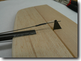
| 113.
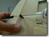
Make a L-bend wire end for the rudder pushrod. Insert it into the horn. Make sure the servo is in neutral, and the rudder is in neutral. |
| 114.
Attach the wire end to the pushrod with a drop of CA and a piece of heat shrink tubing. |
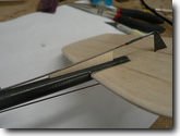
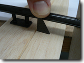
| 115.
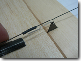
The carbon rod becomes a keeper. Trim the rear end of the rod about 5-8mm past the control horn. |
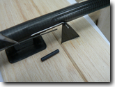
| 116.
Make and install a supporting web from a piece of 1/16" balsa. |
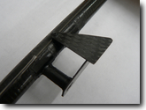
| 117.
Trim the elevator control horn such that the hole is near the center of the tailboom in the installed position. |
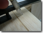
| 118.
Mark the location of the horn on the elevator. The horn must be about 1-2mm away from the boom. |
| 119.
Cut the slit for the control horn. |
| 120.
Insert and glue the control horn. Make an L-bend wire end for the elevator pushrod. |
|
|
|