Taboo XT home
Taboo XL home
Construction notes
Construction tips
Ordering info
IHLGF 2002
HLG seminar
|
This page describes the process of building an aileron wing for
a Taboo XL. The techniques shown here are not specific to
Taboo XL and in large part can be applied to any other HLG
kit, except in places where the supplied hardware dictates
one or the other way of construction (e.g., your control horns
are likely to be different unless you purchase the same ones
that I supply with the kit). For the polyhedral wing, you can
either use the applicable steps in these instructions, or visit
the web-page for the old Taboo kit
and check out the on-line instructions for the polyhedral wing
there. You can also use that page for photos of the fuselage
and tail assembly.
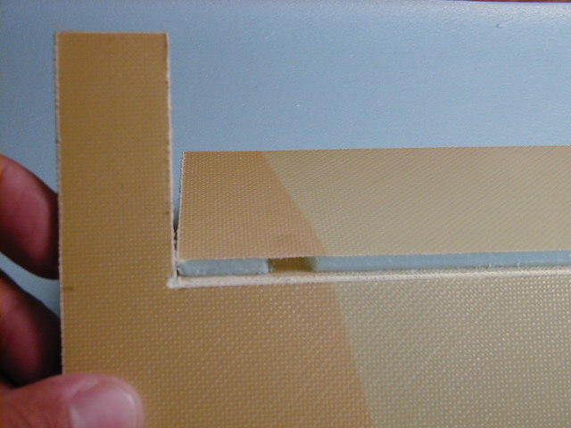
The wing assembly process starts with cutting the servo wells.
The easiest way of cutting nice tight servo wells is to first
cover a small area of the wing skin with masking tape, then
trace the servo outline with a pencil, and cut along the lines
with X-acto knife. Be careful not to damage the top skin.
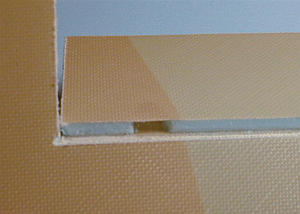
After you have cut the servo wells, prepare the wing root
for joining the panels. Clear and enlarge the wire channels at
the joint. Carve out the foam in the place where the attachment
bolt will go through the wing. These cavities will be filled with the
epoxy-microballoon mixture to form a hard point for the bolt.
|
|
|
Carve out small cavities between the skins of the aileron/flap
in places where the control horns will be installed. You may want
to mark the exact location of the control horns by drawing an
imaginary straight line from the servo arm to the hinge line.
If the control horn ends up being a little off center in
relation to the servo arm, the pushrod will be angled.
|
|
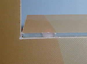
Mix a small batch of 10-15min epoxy and micro-balloons with the consistency
of mayonnaise. Fill the cavities with the mixture, one at a time. Let the
epoxy completely harden before handling the panels.
|
|
|
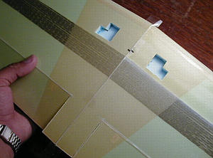
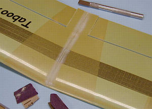
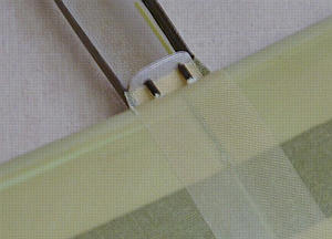
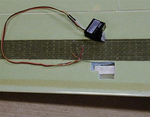
Tape the two wing panels with a clear scotch tape on the bottom
of the joint line. This is the time when you can easily check
the dihedral angle of the wing and correct it if necessary. If the
deviation from the desired angle is small, do not worry about
sanding the bevels. You can simply increase or decrease the force
when gluing the panels together and allow the epoxy-microballoon
mixture to fill the microscopic gap at the joint line. Note the
black marks on the bottom of the wing showing the location of the
servo wire channels.
|
|
Mix another batch of 10-15min epoxy and micro-balloons with the consistency
of mayonnaise. Open the taped wing panels and fill the bolt cavity and cover
the joint with the mixture. Close the joint and squeeze the excess epoxy
out of the joint. You can either wipe off the excess epoxy carefully with
a paper towel, or leave it on the joint and then later break it off with
a flat X-acto knife. Put the wing between two tables or chairs and load up
the joint to apply some pressure while the epoxy sets.
|
|
|
Clean the joint off the hardened epoxy being very careful not
to damage the area around the joint. Refrain from applying any
pressure to the wing surface when cleaning the joint - you will
create visible dents if you do. Sand the skin along the joint line
to remove the shine. Sand the joint line also if you have a small
bump there.
|
|
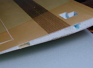
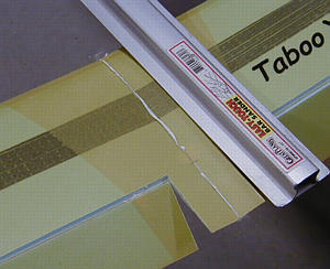
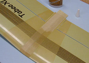
Prepare 2 strips of fiberglass about 40mm wide (kevlar is shown on the
photo, but fiberglass is supplied with the kit currently as it is
much easier to work with and the strength is sufficient). Apply the strips
to the joint by first lightly spraying them with 3M77. Overlap the
top and bottom strips at the leading edge, and simply let them run out at
the trailing edge. Wet out the strips with either thin laminating epoxy or
thin odorless CA glue. Make sure to use a good quality glue (fresh), otherwise
it may not wet out the fiberglass very well and you will end up with dry spots
that cannot be saturated with glue later. Trim off the excess material at the
traling edge after the glue sets.
|
|
|
Place the wing into the fuselage saddle, make sure it is right
in the middle and square to the centerline. Mark the location
of the holes in the fuselage bulkhead on the wing's leading edge.
|
|
Make two holes at the marked locations by twisting an X-acto knife.
Sharpen the ends of the two 0.125" carbon rod pieces. Carefully
insert them into the foam, while twisting them. Leave about 10-15mm sticking
out. Pull out the carbon pegs, and then re-insert them with foam safe CA glue
or epoxy.
|
|
|
Check the alignment of the wing pegs with the holes in the fuselage bulkhead.
Enlarge the holes in the required direction using a small round file.
|
|
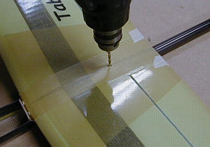
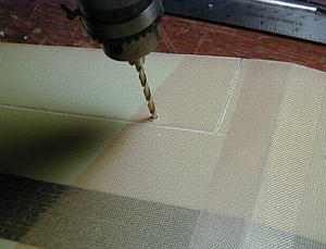
Drill the hole in the wing, then place the wing into the fuselage saddle
and drill the hole in the fuselage deck. Use a smaller diameter drill bit
first suitable for tapping the 8-32 thread. Tap the thread in the fuselage
deck. Soak the thread with thin CA and let it set on its own without
using the CA accelerator, to allow for more penetration into the wood.
Re-tap the thread after the glue is completely set. Enlarge the hole
in the wing for the 8-32 bolt. Cut the nylon bolt to the proper length before
attaching the wing.
|
|
|
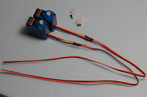
Prepare the wing servos by cutting off the servo leads and soldering the supplied
thin gauge servo wire to them. The tabs were cut off when the servo wells were cut out.
The photo shows HS-55 servos. A very good aileron/flaperon servo is D60 from Dymond
(http://www.rc-dymond.com) - very thin, powerful
and accurate - highly recommended for wing servos.
|
|
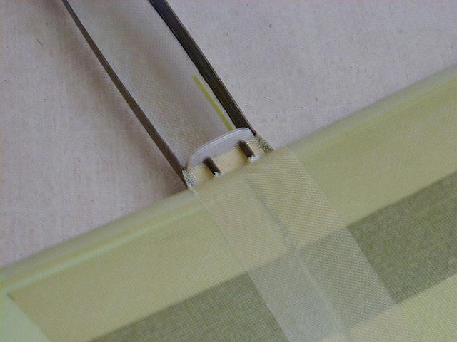
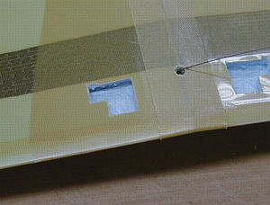
Make a hole for the servo wires at the marked location. Prepare a thin music
wire with a hook on one end for "fishing" the servo wires trough the channels.
Insert the music wire through the channel and pull it out at the aileron servo well.
|
|
|
Hook the servo extension wires to the end of the music wire. Pull them through
the channel and out the hole in the center of the wing.
|
|
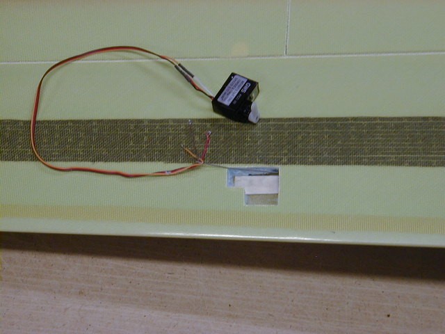
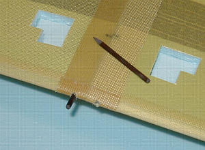
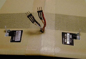
Solder the supplied connectors to the servo wires. The photo shows a 4 servo
wing. All 4 servos are hooked up to 6 pins, all positive and negative wires
are bundled together. For a 2 servo wing you can use either a 4-pin connector
or two 3-pin connectors. Make the wire harness connecting the wing to the
receiver. You will have to connect and operate the servos when installing the
aileron pushrods to make sure that the servos are in neutral position.
|
|
|
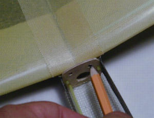
Drill the holes for the aileron control horns using a 1/8" drill bit. Do not
drill through the top skin, although if you do, it's not critical. Cut one
side of the nylon control horn and glue it in the hole with CA.
|
|
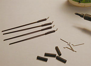
Prepare 2 aileron pushrods (4 in the case of a 4 servo wing) using
0.050" carbon rods and Z-bend ends from a soft steel wire (paper clip
wire). Use small pieces of heat shrink tubing for connecting the wire
ends to the carbon rod. Apply a drop of CA first, slide the heat shrink
tubing over the wire, and heat the tubing with a soldering iron while the
CA is still fresh. Leave one end of the pudhrods infinished.
|
|
|
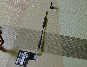
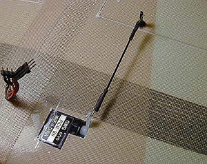
Tape the aileron at the edge to the wing root to keep it in neutral position.
Insert the finished end of the pushrod into the servo arm. Make sure the
servo is in neutral. Insert the second wire end into the control horn. Slide
the heat shrink tubing onto the carbon rod. Apply a drop of CA, join the
carbon rod with the wire end, slide the tubing over the wire end, and shrink
it with a hot soldering iron.
|
|
The finished pushrod is not adjustable. It is imperative that both the servo
and the aileron are in neutral when assembling the pushrod, and the radio
has zero trim settings on all applicable channels. All trim adjustments will
have to be made via the electronic trim on your radio.
Tape the servos in the wells with a scotch tape. Drill the wing tip for the
throwing peg through the carbon spar, and glue the peg (carbon tube) with a
foam safe CA. Your wing is ready for flight tests.
|
|
|